Sunday, May 17, 2015

Shield stabilization

The 15mm copper pipes that shield the H-field antenna against E-field noise are not mounted to the center post in any rigid way. The are just pushed through 15mm holes in the center post and held in place by the blue wire running inside of them and some bare copper wires through small holes in the copper pipes.


The copper pipes can not be pulled out of the center post, but they can still wiggle around. To stiffen the whole antenna assembly I build a cross piece from aluminium and plexiglas.


According to the manual the shield must not cover the complete loop, otherwise the antenna will not work. That is the reason why I build the shield from two semicircles that are connected at the bottom and not connected at the top. The plexiglas acts as an insulator to avoid connecting the semicircles at the top.

Friday, May 1, 2015

Building a shielded H-field loop antenna

The next step after soldering the controller and amplifier boards is building the antennas. I'll start with the H-field antenna. The manual describes two different kinds of H-field antennas that consists of two orthogonal coils:
  • Loop antennas have no core, a big diameter and only a few turns.
  • Ferrite rod antennas have a ferrite core, a small diameter and many turns.
I decided to build a shielded loop antenna with a diameter of 92cm and 8 turns in each loop. The main reason for a loop antenna was that the manual advised against winding my own ferrite rod antenna and suggested buying ready made ones. But that's boring.

Bill of materials:
  • 6m of 15mm soft copper pipe acts as shield against E-field noise
  • 50m of 1.5mm² insulated single-core copper wire (H07 V-U) to form 8 turns in the copper pipe
  • 1m of 75mm plastic pipe acts as center post (not shown)


I build a simple jig out of some scrap wood to help me bending the soft copper pipe into nice and even semicircles with 92cm diameter:


The four copper semicircles are done:


I use a 75mm plastic pipe as center post with 15mm holes 92cm apart to hold all the semicircles. The image shows the top part of the plastic pipe and a semicircle with a wire soldered to it that will be used to ground the shield:


I split the 50m of copper wire into two 25m sections, one for each coil, and prepare it for winding into the copper pipes:


Here is the first loop done with 8 turns in the copper pipe:


The second loop is almost done. I take the prepare copper wire and wind it into the copper pipes basically the same way as you would wind a typical key ring onto a key. My key ring just has 8 turns instead of 2.


Both loops are done. The image shows the antenna upside down. The next steps include testing the antenna with the H-field amplifier and building some kind of stand for it, because it is really unstable and easy to tip right now.


Saturday, July 19, 2014

LCD pins too short

The black plastic spacer on the pin headers of the LCD that goes onto the System RED Controller 10.4 are quite high.


This makes the actual pins quite short. They're so short that they barely make contact in the pin sockets on the controller board. So I just removed the plastic spacer and now the LCD sits much better in the pin sockets.


Thursday, June 19, 2014

HT16K33 interferes with DCF77

I decided to order an Adafruit 1.2" 4-Digit 7-Segment Display w/I2C Backpack and a GA1A12S202 Log-scale Analog Light Sensor for my clock. In the end I want something that works and has the features I need. It doesn't have to be fancy and I don't want to spend too much time on building it. Here's an image showing the current prototype:


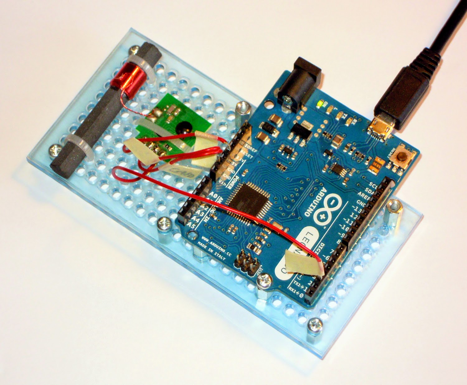
Obviously, it's not showing the current time yet, but just the number of minutes and seconds since the last DCF77 reception error. It seems that the HT16K33 LED controller IC on the back of the 7-segment display interferes with the DCF77 signal. I don't even have to send commands to the IC, simply powering it is enough to cause the issue. I tried different orientations and putting a metal shield in between the two but it didn't help. The only thing that helps is distance. Once I put the DCF77 antenna and the HT16K33 IC about 20cm apart it works. You can see that it worked for more than 49 minutes before I took the picture and stopped the test.

I planned to put all of the clock parts into a simple case made from three pieces of plastic. Well, now I'll need two cases, because I don't want a clock so big that I can get 20cm distance between the IC and the antenna.

Sunday, June 15, 2014

Arduino + DCF77

I've never done something with an Arduino before. So I decided to buy one (an Arduino Leonardo to be precise) along with a DCF77 receiver module. I wrote some simple decoding code for the DCF77 protocol. It worked and you can find it on GitHub.


This was last year. Some weeks ago I got annoyed about the lack of a decent clock on my desk. I have one, but it's not self-illuminated which makes it hard to read during the evening and night when the room is not brightly lit. So I decided to build my own one. It will have the following features:
  • Get its time information from DCF77.
  • Have an illuminated display of some sort to show the current time.
  • Measure the ambient light and adjust the brightness of its display accordingly.
Just these three features, nothing else, probably not even a button. For the DCF77 part I dusted off the Arduino setup mention before and started to improve the code from last year. You can find the current version on GitHub as well.

I originally started the decoder to sample the DCF77 signal at a fixed interval for 10ms, because I could not get it working with interrupts for some reason. This worked well, as the DCF77 signal consists of one 100ms or 200ms long pulse per second. I'll probably keep it this way for the clock because I think that it'll be easier to integrate with the display logic.

I didn't decide on the kind of display yet. I looked at different options:
  • Nixie tubes have a nice old fashioned look, but require high voltages. There are Nixie tube clock kits.
  • As people like the look of Nixie tubes they fake them using edge-lit displays.
  • Another option would be a word clock, such as the QLOCKTWO. There are many people that have build versions of this clock or sell kits, for example here and here.
  • An easy way out would be the typical 7-segment display. Not as creative as a word clock but easy to use and easy to read. There are nice 7-segment clock kits, such as the Alpha Clock Five
I think buying a clock kit of some sort is not an option for me. It is not as interesting as having to solve the problems and challenges on my own. Also the kits I found don't cover my feature list or have way to many features or are just a bit expensive.

The look of the Nixie digits is nice. I already build a prototype of an edge-lit fake Nixie tube but could not make it as bright and clear as I want it to be and gave up on this idea. Here's an image of the prototype:


Tuesday, June 10, 2014

Soldering done

The manual says that the estimated construction time for the controller and the H-field amplifier would be about four hours. Well, it took me the whole weekend.

As I assumed the GPS module was the most tricky to solder, because it doesn't have regular pins but comes in an LCC package that has small pits along the side of its PCB. Took me several attempts to get it soldered without bridges between the pits and between the pits and the metal shield above them.


Compared to the GPS module the amplifier ICs in SOIC-8 packages with normal pins were much easier to solder.


Here's an image of Amplifier 13.1 half done. There is quite a variety of ceramic capacitors on this board. Not difficult to solder, just takes a while.


Because I don't have much more to talk about right now I'll just show more images for the finished boards. The next images show all boards in a top view followed by all boards at an angle to get a good look at all of them.


The next step after soldering is to flash the firmware into the STM32F4 evaluation board and see if all of this actually works. Once that is done I have to build the antennas. I'll start with an H-filed loop antenna.

Saturday, June 7, 2014

Detecting lightning discharges

And now for something completely different...

Last month I read a German news article about the blitzortung.org project. It's about detecting the location of lightning discharges using a network of low budget receiver stations. The clocks of all receiver stations are keep in sync using GPS. This allows to combine the electromagnetic measurements of multiple receivers to calculate the location of a lightning discharge.

I decided to participate in this project and build my own receiver station. So I ordered the basics kits offered by the project founders for the different components of a receiver station. Here's an image showing the red PCBs for the Controller 10.4, the Amplifier 12.3 (H-field) and the Amplifier 13.1 (E-field) with the small Pre-Amplifier 14.1. Each PCB comes with a set of parts that are not easily available from online shops such as Reichelt or Conrad. The green PCB is an STM32F4 evaluation board that sits on top of the Controller 10.4 PCB and runs the firmware for the complete receiver station.


All the rest of the necessary parts can be ordered from Reichelt. There is even an order list with the Reichelt part numbers. Here's an image showing all the parts in a pile.


The next step is to solder all the components to the PCBs. This should not be that hard as most of them are through-hole, but some are SMD such as the GPS module and the amplifier ICs in SOIC-8 packages.